
If your company already manufactures bulbs, panel lights, downlights, or other lighting products, adding LED strip production may look straightforward. Select an LED, choose a voltage, purchase an FPCB, and begin SMT.
In practice, the FPCB cannot be selected in isolation.
Its production format, circuit structure, substrate, copper thickness, board width, cutting interval, and assembly compatibility all need to match the intended LED strip. A board that works for one product may create routing, voltage-drop, soldering, or production problems in another.
In repeated pre-sales discussions, we have found that companies entering LED strip manufacturing often begin with an incomplete request such as:
“Please quote an 8 mm LED strip PCB.”
Width is useful, but it is not enough to define a manufacturable board. Before a meaningful quotation or sample can be prepared, the supplier normally needs to understand the complete product and production context.
This guide shows you how to build that specification step by step.
To specify an LED strip FPCB, define the production format, single- or double-sided structure, substrate material, copper thickness, board width, cutting interval, operating voltage and current, LED package and density, circuit layout, and SMT method. These variables should be evaluated as one system—not as independent purchasing options.
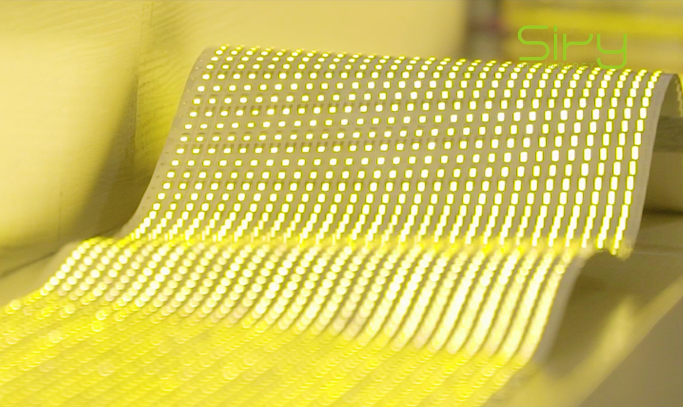
Which Specifications Define an LED Strip FPCB?
An LED strip FPCB specification combines electrical, mechanical, material, and production requirements. The following map shows the main decisions that should be clarified before quotation or sample development.
| Specification | What it affects | Questions to answer |
|---|---|---|
| Production format | Line setup, handling, continuous length, and SMT flow | Panel or continuous roll? What equipment will assemble it? |
| Board structure | Routing space, conductor area, and circuit complexity | Is a single-sided circuit sufficient, or is a double-sided design required? |
| Substrate material | Soldering-process compatibility, flexibility, and cost | What assembly temperature profile and compliance requirements apply? |
| Copper thickness | Current capacity, voltage drop, heat, flexibility, and cost | What voltage, current, power, and operating length are required? |
| Board width | Component layout, routing, and installation space | What LED package and enclosure dimensions must the strip fit? |
| Cutting interval | Installation flexibility and circuit-unit design | How short must each usable segment be? |
| Electrical design | Brightness consistency, power distribution, and reliability | What is the target voltage, current, wattage, and maximum run length? |
| SMT compatibility | Placement accuracy, throughput, and production stability | Will you use panel SMT, roll-to-roll SMT, or another placement method? |
The important point is not to choose the “highest” specification in each row. It is to choose a coordinated set of specifications for the product you intend to manufacture.
Which LED Strip FPCB Production Format Should You Choose?
LED strip FPCBs are commonly supplied in several manufacturing formats:
- 0.5 m panel FPCB
- 1 m panel FPCB
- Continuous roll-to-roll FPCB
“Roll-to-roll” describes a manufacturing format, not a different base material. The circuit is produced in a continuous roll, which can support long-length processing and continuous SMT without the panel joints associated with short-board formats.
Choose the production format according to the SMT equipment, target output, required circuit length, material-handling method, and downstream manufacturing process.
When panel FPCB may be appropriate
Panel formats can be practical when:
- The existing SMT line is configured for panels
- Production volumes are moderate
- Operators are familiar with panel handling
- The product or process does not require a long continuous circuit
When roll-to-roll FPCB may be appropriate
Continuous FPCB can be useful when:
- The SMT line supports continuous material feeding
- The manufacturer needs long strip lengths without panel-to-panel joints
- High-volume production and material flow are important
- Downstream splitting, extrusion, or encapsulation processes are designed for continuous strip
Roll-to-roll is not automatically better for every factory. The correct format depends on the equipment, target output, operator experience, product length, and downstream process. For a new LED strip line, confirm the FPCB format with both the board supplier and the SMT equipment provider before purchasing tooling or materials.
Should You Use a Single-Sided or Double-Sided FPCB?
The layer structure should follow the circuit—not a general assumption that more layers always mean better performance.
A single-sided FPCB may be sufficient for a relatively simple circuit, while a double-sided design may be appropriate when the product needs more routing or conductor space.
Single-sided FPCB
A single-sided FPCB places the conductive circuit on one side of the flexible base material. It is commonly considered when routing is relatively simple and the electrical requirements can be met with the available conductor area.
Potential advantages include:
- Simpler construction
- Straightforward production for suitable designs
- Potential cost efficiency
Double-sided FPCB
A double-sided FPCB provides conductive layers on both sides, connected where the circuit design requires. The additional routing space can help when:
- The circuit is more complex
- More conductor area is needed
- Component density limits routing on one layer
- Voltage-drop or current-distribution requirements cannot be resolved efficiently on a single side
Do not decide the layer count from voltage alone. Two strips with the same working voltage can have different power, density, run-length, thermal, and routing requirements. The circuit calculation and layout should justify the final structure.
How Should You Select the FPCB Substrate?
Polyimide (PI) and polyester (PET) are two substrate families commonly discussed for flexible circuits. The useful question is not “Which material is better?” but “Which material system fits the intended assembly and product?”
Select the substrate by reviewing the exact material construction, soldering profile, product environment, compliance requirements, and cost target together.
| Selection factor | Why it matters |
|---|---|
| Soldering process | The complete material stack must tolerate the actual soldering profile |
| Lead-free production | The selected construction needs to match the required process conditions |
| Product environment | Bending, installation, thermal exposure, and service conditions may affect selection |
| Compliance needs | Material declarations and recognized constructions may be project-specific |
| Cost target | Material choice must be balanced against manufacturing and product requirements |
In pre-sales conversations, customers often ask us to recommend PI or PET before describing their process. We normally begin by clarifying the soldering method, temperature profile, target market, compliance requirements, application, and cost objective.
Specific temperature capability should always be confirmed against the supplier’s material datasheet and the finished FPCB construction. A general temperature value for “PI” or “PET” should not replace validation of the exact material system.
Practical check: Share your reflow profile—or at least the planned soldering process—with the FPCB supplier before approving the substrate.
How Do Electrical Requirements Affect Copper Thickness?
Copper thickness is an electrical and manufacturing decision. It should be selected after the target strip has been defined.
Copper thickness should be evaluated together with operating voltage, current, power, feed length, trace geometry, heat dissipation, flexibility, and circuit structure.
The main inputs include:
- Operating voltage
- Current per circuit or per meter
- Power per meter
- Maximum continuous strip length
- Acceptable voltage drop
- Copper-trace width and layout
- Heat dissipation conditions
- Flexibility requirements
Higher current or a longer operating length may require more conductor capacity, but thicker copper is only one possible design response. Trace width, parallel paths, circuit segmentation, feed method, and layer structure can also affect the result.
For this reason, a rule such as “this voltage always uses this copper thickness” is unreliable. Working voltage does not tell the supplier the total current, strip power, or trace geometry.
Information to provide for copper evaluation
Instead of requesting “standard copper,” provide:
- Working voltage
- Target watts per meter
- LED and resistor configuration
- LEDs per meter
- Maximum powered length
- Board width
- Expected installation and heat-dissipation conditions
The supplier can then evaluate copper thickness together with the circuit design. Final electrical and thermal performance should be confirmed through sample testing under the intended operating conditions.
How Should You Choose the Board Width?
LED strip FPCBs are available in many widths. Common project discussions may involve narrow boards for compact channels and wider boards for larger packages, denser layouts, or additional routing, but there is no single correct width for all LED strips.
Choose the board width around the LED package, component layout, copper routing, solder pads, waterproofing process, connector, and installation channel.
Board width is usually influenced by:
- LED package dimensions
- LED and component arrangement
- Number and width of copper traces
- Single-color, CCT, RGB, RGBW, or addressable circuit requirements
- Connector and solder-pad dimensions
- Silicone extrusion, encapsulation, or waterproofing process
- Aluminum profile or installation-channel dimensions
Selecting the narrowest possible board can make routing, current distribution, SMT placement, and solder-pad design more difficult. Selecting a wider board than the application needs can increase material use or prevent the strip from fitting its intended channel.
The enclosure, FPCB, component layout, and production process should therefore be reviewed together.
Why Does the LED Strip Cutting Interval Matter?
The cutting interval is the smallest circuit unit that can be separated and still operate as designed. It directly affects how precisely installers can fit the finished strip to a project.
A shorter cutting interval can improve installation flexibility, but it also changes the electrical grouping, component arrangement, pad locations, routing, and SMT tolerance.
Shorter cutting units can be useful in:
- Cabinet and shelf lighting
- Architectural details
- Signage and decorative lighting
- Curved or irregular installations
- Products marketed for precise or free-cut applications
However, a shorter interval is not created by moving the printed scissors symbol. It can change:
- The number of LEDs and resistors in each circuit unit
- Pad placement
- Current paths
- Component spacing
- Routing complexity
- SMT placement tolerance
- Product cost
The cutting unit must be designed as part of the electrical circuit. It should also leave pads that are practical for connection after cutting.
How Do You Confirm SMT and Downstream Process Compatibility?
An FPCB drawing can be electrically correct but still be inconvenient to manufacture. Manufacturability should be reviewed before tooling and mass production.
Confirm that the FPCB format, pads, positioning features, component spacing, material system, and board dimensions match both the SMT line and every downstream process.
LED strip assembly may use:
- Panel SMT
- Continuous roll-to-roll SMT
- Group Pick & Group Place methods for suitable standard products
- High-precision placement systems for IC-based, addressable, COB, or dense layouts
Before approving the board, check:
- Does the panel or roll format fit the line?
- Are fiducials and positioning features suitable for the equipment?
- Are pads compatible with the selected LED and resistor packages?
- Is component spacing practical for placement and reflow?
- Can the strip be inspected, repaired, split, and tested efficiently?
- Will the width and material construction fit extrusion or encapsulation?
- Can the same settings and material control be maintained in volume production?
This last question matters. A successful hand-built or short-run sample does not automatically prove that the design is ready for stable mass production.
Which LED Strip FPCB Specification Mistakes Should You Avoid?
The most common mistakes come from treating individual specifications as isolated purchasing choices instead of parts of one product and manufacturing system.
Treating the FPCB as a standard commodity
Requests based only on voltage and width leave critical electrical and manufacturing variables undefined. Two boards described as “12 V, 8 mm” may have different circuits, copper, materials, cutting units, and assembly suitability.
Assuming the highest specification is always safest
Double-sided construction, thicker copper, PI material, or continuous production may be valuable in the right project. They can also add cost or process requirements without solving the actual design problem.
Comparing quotations with different specifications
A lower price may reflect a different material stack, copper specification, production format, testing scope, tooling condition, or order quantity. Normalize the technical specification before comparing suppliers.
Finalizing the PCB before the LED strip BOM
LED package, resistor package and value, density, voltage, wattage, and cutting unit affect the circuit layout. Changing them later can require a board redesign.
Ignoring downstream production
The FPCB must pass through printing, placement, reflow, inspection, splitting, and—where applicable—extrusion or encapsulation. A design decision made at the circuit stage can create a problem several processes later.
What Information Should an LED Strip FPCB RFQ Include?
Use this checklist before requesting a quotation or starting sample development.
A usable RFQ should identify the intended product, electrical conditions, mechanical dimensions, board construction, component information, production process, reference files, and order plan.
| RFQ field | Information to prepare |
|---|---|
| Intended product | Single color, CCT, RGB, RGBW, COB, addressable, high voltage, or another type |
| Production format | 0.5 m panel, 1 m panel, continuous roll, or request a recommendation |
| Board structure | Single-sided, double-sided, or to be evaluated |
| Substrate/material requirement | PI, PET, specified construction, compliance need, or process conditions |
| Copper requirement | Existing specification or electrical data for evaluation |
| Working voltage | Nominal input voltage |
| Power/current | Watts per meter and/or current data |
| LED information | Package, part number where available, and LEDs per meter |
| Other components | Resistor/IC package and circuit configuration |
| Board width | Target width and installation-space limit |
| Cutting interval | Required cut length or number of LEDs per circuit unit |
| Maximum run length | Intended powered length and feed method |
| Circuit files | Schematic, Gerber, drawing, sample, or request for design support |
| SMT process | Panel or roll-to-roll equipment, placement method, and reflow information |
| Downstream process | Splitting, waterproofing, extrusion, encapsulation, connector, or profile requirements |
| Order plan | Sample quantity, estimated volume, target schedule, and destination market |
If some fields are still unknown, mark them as “to be recommended” and share the intended finished product, production equipment, and target application. That gives the supplier a reliable starting point for technical discussion.
How Does FPCB Selection Support Stable LED Strip Production?
For an established lighting manufacturer, the biggest challenge in adding LED strips is not simply purchasing an SMT line or sourcing a board. It is turning equipment, materials, circuit design, and process control into repeatable production.
The FPCB sits at the center of that system. It connects the electrical design to component placement, heat and voltage-drop behavior, cutting flexibility, and downstream manufacturing.
NWSIRY specializes in flexible circuit board solutions for LED strip manufacturing, including circuit-layout support, customized LED strip FPCB, roll-to-roll physical-cutting FPCB, and production-compatibility support. Our role during specification is to help manufacturers translate a product idea into a board that can be sampled, tested, and prepared for scalable production.
Planning a new LED strip product or production line? Send us your target voltage, LED package, LED density, board width, cutting interval, power requirement, and SMT method. If the specification is not yet complete, tell us what you plan to manufacture and which equipment you have—we can begin from there.
Discuss Your LED Strip FPCB Project
Email: [email protected]
Website: www.nwsiry.com
Frequently Asked Questions
What information is needed to quote an LED strip FPCB?
A useful quotation normally requires the production format, circuit structure, substrate or process requirement, copper thickness or electrical data, board width, working voltage, power/current, LED package and density, cutting interval, circuit layout, and SMT method. Order quantity and tooling requirements may also affect the quotation.
Is roll-to-roll FPCB better than panel FPCB?
Not in every case. Roll-to-roll FPCB can support continuous SMT and long-length production, while panel FPCB may fit existing equipment and moderate production needs. The suitable format depends on the factory’s line configuration, output target, product length, and downstream process.
Should an LED strip use a single-sided or double-sided FPCB?
The decision depends on routing complexity, conductor-area requirements, component density, voltage-drop targets, and cost. A single-sided board may be sufficient for a straightforward circuit; a double-sided board may be appropriate when additional routing or conductor space is needed.
Is PI always better than PET for LED strip FPCB?
No. Substrate selection should match the exact material construction, soldering profile, product application, compliance requirements, and cost target. Confirm process compatibility using supplier data for the specific material system.
Does a higher-voltage LED strip always need thicker copper?
No. Copper selection is influenced by current, power, run length, trace geometry, voltage-drop target, thermal conditions, and circuit structure. Voltage alone is not enough to specify copper thickness.
Why does the LED strip cutting interval matter?
The cutting interval determines the smallest usable circuit segment. A shorter unit can improve installation flexibility, but it also affects circuit design, component arrangement, pad location, routing, and manufacturing tolerance.
Can an FPCB supplier help if the circuit drawing is not finished?
Yes. A specialist supplier may be able to support circuit layout and manufacturability review when given the intended product, LED and component information, voltage, power, dimensions, cutting requirement, and production process.
Conclusion
An LED strip FPCB is not a standardized flexible carrier with one universal specification. It is the electrical and manufacturing platform that connects the component layout, circuit structure, material selection, copper design, board dimensions, cutting units, and production process.
Before comparing quotations, define as many of these inputs as possible and clearly label the remaining decisions as provisional or “to be recommended.” This gives the buyer and supplier a shared technical baseline for sample development and mass-production planning.
If you are preparing a new LED strip product or adding LED strip production to an existing lighting factory, send NWSIRY your product concept, drawings, BOM, component information, or reference sample. We can help organize the missing FPCB requirements and prepare a clearer path toward design review, sampling, and quotation.